Introduction
When a vehicle GNSS system works well on a bench or in open sky but becomes unstable after installation, replacing the antenna should not be the first response. Mounting conditions, vehicle electronics, cable faults, correction data and receiver configuration can create similar symptoms. Drawing on Harxon's experience in high-precision GNSS and vehicle antenna integration, this guide presents a controlled diagnostic workflow for locating the actual source of lost accuracy. The goal is to determine whether the problem lies in the antenna, installation, RF connection, electronic environment or positioning system before making hardware changes.
Quick Answer
First define the exact symptom and record an open-sky baseline. Then change one variable at a time: move the antenna temporarily, switch vehicle electronics on and off, substitute a known-good cable, verify antenna power, and review receiver and correction logs. An improvement after moving the antenna points to installation or multipath. A repeatable change when another system is activated suggests interference. Healthy satellite signals with unstable RTK usually indicate correction, timing or configuration problems. Replace the antenna only when controlled tests show that it cannot meet the requirement in an otherwise verified system.
Define the Problem Before Changing Hardware
“Poor GNSS accuracy” is too broad to support effective troubleshooting. A drifting position, low signal level, repeated RTK float and delayed recovery after a tunnel may have different causes.
Before testing, record:
- Where the problem occurs
- Whether the vehicle is stationary or moving
- Which electronic systems are active
- Whether all frequencies are affected
- Whether the issue changes with vehicle direction
- Whether satellite reception or only RTK status is unstable
- Whether the problem can be reproduced
The same symptom should appear under the same conditions before it is treated as a confirmed fault.
Match the Symptom to the First Test
| Observed symptom | Likely area to investigate | First diagnostic test |
|---|---|---|
| Signal quality is low in every environment | Antenna power, cable, connector or hardware compatibility | Check power and substitute a known-good RF path |
| Performance falls mainly near buildings | Multipath or non-line-of-sight signals | Compare open-sky and obstructed-route data |
| Accuracy changes with vehicle heading | Obstruction, mounting asymmetry or nearby structures | Repeat the same route in opposite directions |
| GNSS degrades when another system is active | Electromagnetic interference | Perform controlled electronics on/off testing |
| Satellite signals are healthy but RTK is unstable | Corrections, receiver settings or synchronization | Review correction and receiver logs |
| Performance worsens only after final assembly | Covers, glass, brackets, wiring or nearby electronics | Compare pre-assembly and final-assembly configurations |
This initial classification prevents unrelated settings from being adjusted at the same time.
Check 1 — Establish an Open-Sky Baseline
Begin in an open area away from buildings, overhead structures, large vehicles and other reflective objects. Keep the vehicle stationary and, where practical, switch off nonessential communication and high-power electronic systems.
Record:
- Satellites tracked and used
- Signal quality by frequency
- Position mode
- RTK fixed or float status
- Time to first fix
- Static position repeatability
- Correction-data availability
- Correction age or latency
- Receiver warnings
- Antenna-power or short-circuit alarms
The purpose is not to apply one universal pass threshold. It is to create a reference for the same system before changing one installation or configuration variable.
What the Baseline Reveals
If performance is already poor in open sky, investigate the RF connection, antenna power, receiver configuration and hardware compatibility before studying urban multipath.
If the open-sky baseline is stable but performance deteriorates only after movement or in specific locations, the problem is more likely connected to installation, interference or operating environment.
Check 2 — Test a Temporary Clear Antenna Position
Temporarily move the antenna to a position with a clearer view of the sky, commonly near the unobstructed central area of the roof. Keep the receiver, correction source, cable type and software settings unchanged.
The temporary position does not need to be the final production location. It is a diagnostic reference.
Interpret the Result
A clear improvement suggests that the original position is affected by one or more of the following:
- Partial sky blockage
- Roof-edge reflections
- A roof rack or light bar
- A sunroof frame
- A nearby sensor housing
- Another antenna
- An unsuitable mounting surface
- An asymmetric enclosure or ground plane
- Metallic or heated glass
No meaningful improvement suggests that the main cause may lie in the cable, active-antenna power, receiver, correction stream or wider electronic system.
Repeat the Comparison
Do not rely on one short observation. Compare both positions under the same satellite conditions and vehicle operating state. Where possible, repeat the test to confirm that the change is consistent.
Check 3 — Separate Multipath from General Signal Loss
Multipath occurs when reflected GNSS signals reach the antenna after travelling along a longer path. In dense urban environments, direct signals may also be blocked, leaving the receiver to use reflected or non-line-of-sight signals.
Vehicle-generated reflections may come from:
- Roof edges
- Sunroof structures
- Metal brackets
- Sensor housings
- Nearby antennas
- Large body panels
Environmental reflections may come from:
- Tall buildings
- Bridges
- Road signs
- Sound barriers
- Large trucks
- Metal fences
Use Route-Based Comparison
Compare performance on:
- An open road
- A street beside tall buildings
- A route beneath bridges
- A tree-covered road
- The same route in both directions
If errors appear mainly in reflective environments while open-sky reception remains stable, the issue is more likely multipath or signal blockage than a general antenna failure.
If signal quality changes noticeably when the vehicle changes heading, inspect the antenna position and surrounding structure for directional shielding or reflection.
RTK corrections can reduce several common GNSS errors, but they cannot fully remove reflections generated close to the vehicle antenna.
Check 4 — Test Vehicle Electronics for Interference
GNSS signals are weak when they arrive at the antenna. Noise from other vehicle systems can reduce receiver sensitivity even when those systems do not transmit directly inside a GNSS band.
Possible sources include:
- Cellular communication systems
- Wi-Fi and Bluetooth modules
- C-V2X or DSRC equipment
- Displays
- Cameras
- Computing platforms
- DC/DC converters
- Inverters
- Electric motors
- Motor controllers
- High-voltage systems
- Power and data cables
Use a Controlled On/Off Test
Activate one system at a time while monitoring:
- Signal quality by frequency
- Satellites tracked and used
- Receiver warnings
- Position mode
- RTK status
- Recovery time after the system is switched off
A suspected interference source should produce a repeatable change. If performance falls each time one system is activated and returns when it is disabled, investigate:
- Antenna separation
- Cable routing
- Grounding
- Shielding
- Filtering
- Power-supply noise
- Receiver desensitization
Physical proximity alone does not prove interference. The relationship should be demonstrated through repeatable testing.
Test Real Operating Combinations
After testing individual systems, repeat relevant combinations. A vehicle may perform normally when cellular and propulsion systems are tested separately but degrade when both operate at high load.
Harxon vehicle solutions may combine positioning and communication functions in compact structures, but the complete installation still requires suitable isolation, grounding and RF coexistence verification.
Check 5 — Inspect the Complete RF Connection
A suitable antenna cannot compensate for a damaged cable, unstable power supply or poorly installed connector.
Inspect the complete path:
Antenna → Cable → Connectors and adapters → Receiver
Check for:
- Excessive cable length
- Unexpected cable loss
- Sharp bends
- Compression or abrasion
- Moisture ingress
- Loose connectors
- Partially engaged connectors
- Incorrectly installed terminals
- Excessive adapters
- Cable routing beside noisy power lines
- Unstable antenna supply voltage
- Receiver voltage outside the antenna requirement
- Intermittent faults during vibration
Substitute One Component at a Time
Where practical, compare the installed connection with:
- A known-good short cable
- A known-good connector
- A verified receiver input
- A stable antenna power source
- A known-good antenna of the same intended type
Change only one item during each comparison. Replacing the antenna, cable and receiver together may improve the result, but it will not identify the failed component.
Include Dynamic Conditions
Some connection faults appear only while the vehicle is moving. Repeat the inspection under vibration, steering movement and normal cable loading when safe to do so.
If a shorter or known-good cable improves reception, repair or redesign the RF connection before selecting another antenna.
Check 6 — Review Corrections and Receiver Configuration
Strong satellite signals do not guarantee stable high-precision positioning. A vehicle may receive GNSS signals normally while remaining in RTK float because the correction stream, receiver settings or sensor configuration is incorrect.
Verify:
- Required constellations and frequencies are enabled
- The receiver supports the active antenna configuration
- Antenna power and fault detection are enabled correctly
- RTK or PPP corrections are available
- Correction format is supported
- Correction age remains acceptable for the system
- Network or radio corrections are received continuously
- The elevation mask is not excluding too many satellites
- The dynamic model is suitable for vehicle motion
- GNSS, IMU and vehicle data are synchronized
- The antenna lever arm is entered correctly
- Coordinate frames are defined consistently
For dual-antenna systems, also verify:
- Antenna spacing
- Baseline length
- Left-right or front-rear orientation
- Cable assignment
- Heading configuration
- Phase-center positions
- Relationship to the vehicle coordinate system
Separate RF Health from Positioning Status
If signal quality and tracked-satellite counts remain healthy while RTK repeatedly changes from fixed to float, focus first on:
- Correction interruptions
- Correction latency
- Receiver configuration
- Timing
- Sensor synchronization
- Lever-arm or coordinate errors
Replacing the antenna is unlikely to solve a correction or configuration problem.
Check 7 — Repeat the Test on a Controlled Route
After the stationary tests, use a repeatable road route to compare the system under movement.
Include representative sections such as:
- Open roads
- Urban streets
- Bridges
- Trees or partial blockage
- Low-speed operation
- Higher-speed operation
- Different vehicle headings
Keep the receiver configuration, correction source and recording method unchanged.
Record Enough Context
GNSS position output alone is not sufficient. Record:
- Time and location
- Vehicle speed
- Vehicle heading
- Signal quality
- Satellites used
- DOP
- RTK status
- Correction age
- Receiver warnings
- Electronic systems active
- Antenna and cable configuration
This makes it possible to connect each accuracy loss to a specific vehicle state or environment.
Confirm Repeatability
A single error on one route is not enough to prove a hardware problem. Repeat the route and look for patterns:
- Does the error occur at the same location?
- Does it occur in both directions?
- Does it appear at the same vehicle speed?
- Is it linked to one electronic system?
- Does it disappear after changing the antenna position or cable?
Repeatable patterns provide stronger evidence than isolated position jumps.
Use the Results to Choose the Correct Action
| Test result | Most likely area | Priority action |
|---|---|---|
| Temporary clear position improves performance | Original mounting location or surrounding structure | Redesign the location, enclosure or nearby structure |
| Performance falls when one device is activated | RF interference | Improve isolation, routing, filtering or grounding |
| Known-good cable improves reception | Cable or connector fault | Repair or redesign the RF path |
| Open-sky performance is poor in all configurations | Antenna, power, cable or receiver compatibility | Verify the complete receiving chain |
| Performance mainly falls near buildings | Multipath or non-line-of-sight reception | Improve placement and evaluate operating limitations |
| Signals are healthy but RTK remains unstable | Corrections or configuration | Review correction, timing and receiver settings |
| Fault appears only after final assembly | Vehicle materials or installed electronics | Retest covers, glass, brackets, wiring and nearby systems |
| A known-good antenna resolves the fault while all other variables remain fixed | Original antenna limitation or damage | Inspect or replace the antenna |
When Should the Antenna Be Replaced?
Replacing the antenna is justified when controlled comparisons show that:
- It does not receive the required enabled frequencies correctly.
- Active-antenna power is correct but output remains abnormal.
- A known-good antenna resolves the issue under identical conditions.
- The antenna has physical, connector or sealing damage.
- Its filtering cannot tolerate the verified vehicle RF environment.
- Its installed performance remains inadequate after the mounting and RF path have been corrected.
Antenna replacement should be the conclusion of the diagnostic process rather than the starting assumption.
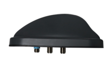
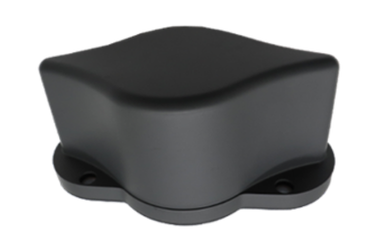
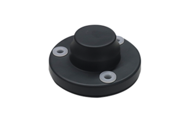
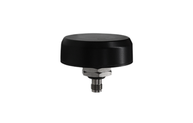
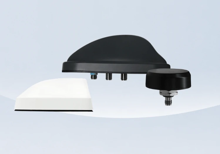
When a different structure is required, Harxon’s vehicle antenna portfolio includes standalone high-precision designs and integrated communication and navigation configurations for different installation requirements. The replacement should be evaluated under the same controlled conditions used to identify the original limitation.
Diagnostic Record Template
A simple record can prevent test results from becoming difficult to compare.
| Test item | Configuration | Environment | Result | Interpretation |
|---|---|---|---|---|
| Open-sky baseline | Final receiver settings | Open area, stationary | Record GNSS and RTK data | Establish reference |
| Temporary position | Antenna moved, other settings fixed | Same open area | Compare with baseline | Check mounting influence |
| Electronics test | One device activated at a time | Stationary | Record repeatable changes | Identify interference |
| RF-path test | Known-good cable or connector | Same position | Compare signal data | Check connection loss |
| Correction test | Correction stream and logs reviewed | Stationary and moving | Compare RTK status | Check non-RF causes |
| Controlled route | Final test configuration | Repeated route | Compare locations and headings | Confirm real-world pattern |
Conclusion
Poor vehicle GNSS accuracy should be diagnosed by isolating variables rather than replacing components by assumption. Begin with a repeatable open-sky baseline, then test antenna position, multipath conditions, vehicle electronics, the RF connection, corrections and receiver configuration separately.
The resulting pattern should show whether the correct response is to change the installation, control interference, repair the cable, correct system settings or replace the antenna. This evidence-based process reduces unnecessary hardware changes and produces a correction that can be verified on the complete vehicle.
FAQ
How long should a vehicle GNSS diagnostic test last?
The test should include repeated stationary and road measurements under different satellite conditions, headings and operating states. One short open-sky test may establish a baseline, but it is not enough to confirm an intermittent or environment-dependent fault.
What data should be exported from the receiver?
Useful records include signal quality by frequency, tracked and used satellites, DOP, position mode, RTK status, correction age, receiver warnings and timestamps. Vehicle speed, heading and active electronic systems should be recorded alongside the GNSS data.
Should the system be retested after final vehicle assembly?
Yes. Glass, covers, brackets, wiring, sealants and nearby electronics may change the RF environment. Testing should be repeated using the final production enclosure, cable route and vehicle configuration.
How should intermittent faults be investigated?
Look for conditions shared by every occurrence, such as vibration, temperature, vehicle speed, steering movement or activation of a specific electronic system. Continuous logs are more useful than isolated workshop measurements.
When is chamber or OTA testing useful?
Chamber or OTA testing is useful when road tests reveal a repeatable RF problem but cannot isolate its source. It can help evaluate antenna efficiency, radiation behavior, isolation and receiver desensitization under controlled conditions.