Introduction
GNSS antenna datasheets typically list gain and axial ratio. Datasheets for active antennas may also include LNA gain and noise figure. These specifications help narrow down antenna options, but cannot fully describe how a GNSS device will perform after installation. Mounting position, ground plane, cable, nearby electronics, and obstructions in the operating environment can all affect signals received by the device.
Field testing shows how a candidate antenna performs in its intended device. Start with an open-sky baseline, then repeat testing in environments that reflect actual use. Comparing signal reception and positioning results across those conditions gives you a firmer basis for antenna selection.
What GNSS Antenna Specifications Tell You
Before field testing, review these specifications alongside their measurement conditions:
- Antenna element gain: Shows how strongly an antenna receives signals from a given direction. A radiation pattern shows how gain changes as satellites move across the sky.
- Axial ratio: Indicates how well an antenna receives right-hand circularly polarized GNSS signals. Values at different elevation angles and frequencies provide a fuller picture than a single measurement.
- Phase center: Refers to the effective point used for carrier-phase measurements. For high-precision work, check phase center offset and its variation with satellite direction and frequency.
- LNA gain: In an active antenna, a low-noise amplifier boosts received signals. Account for cable loss and other gains or losses in the RF path, then check whether gain at the receiver input meets receiver requirements.
- Noise figure: Describes noise added by an amplifier. A lower value means less added noise, but does not account for noise and interference received by the antenna.
- Frequency coverage: Lists supported GNSS bands. Match those bands to signals used by the receiver, and check performance across required bands.
Taken together, these specifications help identify candidates for field testing. Use the intended mounting arrangement for the final comparison, since installation can affect antenna performance.
Key Metrics for Real-World GNSS Testing
Field testing should capture both signal reception and positioning results. Some metrics describe signal quality and tracking continuity; others reflect performance of the complete positioning system under test conditions.
- C/N0: Carrier-to-noise density ratio indicates the quality of signals tracked by a receiver. Compare the same satellite signals over similar time periods, and record satellite elevation when interpreting differences.
- Satellite tracking stability: Record how many satellites remain tracked and whether signals are repeatedly lost and reacquired. These observations show how tracking holds up as surroundings change.
- Time to First Fix (TTFF): Measures time from a defined start point to a position fix. Use the same start condition, assistance data, and timing method for each test.
- RTK Fixed availability: Record the proportion of test time spent in an RTK Fixed solution, along with interruptions and recovery time. Correction data, receiver processing, and satellite visibility also affect this result.
- Positioning accuracy: Compare static positions with known coordinates, or dynamic positions with a time-synchronized reference trajectory. Report test conditions and distinguish horizontal from vertical error where relevant.
- Repeatability: Repeat measurements at the same location or along the same route to see how consistent results are. A single accurate fix does not show whether a device can produce similar results consistently.
C/N0 and satellite tracking stability mainly describe signal reception. TTFF, RTK Fixed availability, positioning accuracy, and repeatability reflect behavior of the complete positioning system. Consider these metrics together when comparing antennas.
How to Conduct Effective GNSS Field Tests
Begin with an open-sky baseline, then compare antennas in environments the device will encounter during use.
- Establish an open-sky baseline. Mount the antenna as it would be used on the device and test at a location with minimal obstruction. For static accuracy testing, use a point with known coordinates. Record mounting position, antenna orientation, ground plane, receiver settings, cable, and correction source.
- Compare antennas under consistent conditions. Keep receiver, firmware, cable, and differential correction setup consistent when switching antennas. Alternate between candidates in runs of equal duration over similar time periods. For dynamic tests, follow the same route at a similar speed. Record any mounting differences required by each antenna.
- Test representative environments. Repeat comparisons near buildings, under tree cover, and in other conditions typical of the device’s use. Record signal loss and, where applicable, RTK Fixed interruptions. After an obstruction, measure time to reacquire satellite signals and, where applicable, time to regain RTK Fixed separately.
- Collect static and dynamic data. At fixed points, record C/N0, tracking continuity, RTK Fixed availability where applicable, and the spread of position results. On repeatable routes, record tracking interruptions and recovery time. If a time-synchronized reference trajectory is available, record trajectory error as well. Compare static results across open-sky, obstructed, and other representative environments. Make the same cross-environment comparison for dynamic results. When comparing positioning accuracy across environments, use reliable reference data for each test.
From Test Results to Antenna Selection

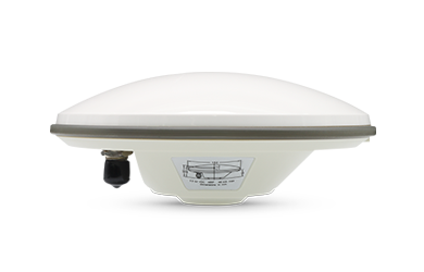
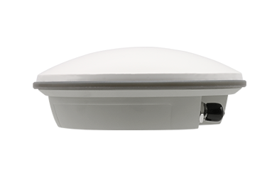
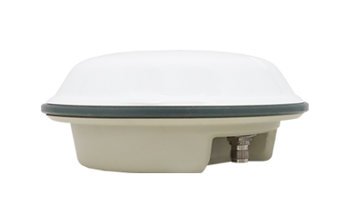
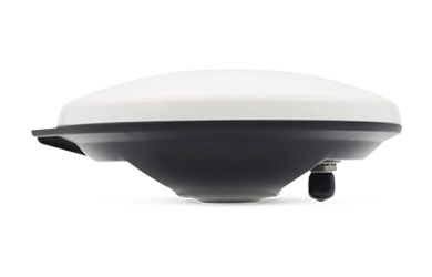
Harxon HX-SE401A survey GNSS antenna.
Interpret field results according to how each device will be used.
- Surveying RTK receivers: Focus on position repeatability and RTK Fixed stability. Compare repeated measurements and the proportion of time a receiver maintains a Fixed solution in environments where surveying work will take place.
- OEM devices with built-in antennas: Focus on installation effects in the complete device. Test candidates in the intended enclosure and mounting position, with nearby electronics operating, to see how the integrated device performs.
- Vehicle-mounted devices: Focus on performance during movement. Test along representative routes and compare tracking continuity and positioning results as a vehicle passes through open and obstructed areas.
Select an antenna that meets relevant performance requirements, supports GNSS bands used by the device, and fits its size, mounting, and cable constraints.
Conclusion
Select a GNSS antenna based on performance in its intended device and operating environment. Compare candidates under consistent conditions, then focus on results relevant to the application: RTK Fixed stability and repeatability for surveying, installation effects for OEM devices, and performance during movement for vehicles. Datasheet specifications help narrow the options; field results guide the final choice.
CTA
Selecting a GNSS antenna for a surveying receiver, an OEM device, or a vehicle? Share your required GNSS bands, mounting space, receiver configuration, and operating conditions with Harxon. We can help identify suitable antenna options and plan field tests around your installation and use case.
FAQ
1. Does higher antenna element gain always mean better field performance?
No. Element gain varies with signal direction. Check the radiation pattern and compare candidates in the intended device and operating environments.
2. Can C/N0 alone show which antenna provides better positioning?
No. C/N0 helps compare tracked signal quality, but positioning also depends on satellite visibility, receiver processing, and, for RTK, correction data. Check tracking continuity, positioning accuracy, and RTK Fixed availability where applicable.
3. Why test an OEM antenna in the complete device?
Enclosure, mounting position, ground plane, and nearby electronics can affect reception. Testing in the complete device shows how an antenna performs under its intended operating conditions.
4. How long should a GNSS field test run?
Test duration depends on the device and its operating conditions. Run and repeat tests long enough to cover typical conditions, including obstruction and recovery. Record the duration of each run and use consistent conditions when comparing antennas.