Introduction
Choosing a choke ring antenna is not simply a matter of selecting the largest design or the highest gain value. The right choice depends on the site, multipath exposure, calibration requirements, supported signals, receiver compatibility and mounting limits. Because these conditions vary between installations, Harxon draws on its expertise in high-precision GNSS antenna design to provide 3D, 2D and mini choke ring options for different reference and monitoring needs. This guide explains how to determine whether a choke ring is necessary and compare available designs without assuming that size or structure alone determines positioning performance.
Quick Answer
Start with the application and installation site. A full-size 3D choke ring is generally considered when a permanent station has sufficient space and support capacity and places strong emphasis on low-elevation tracking and multipath control. A 2D design can reduce height and weight while retaining a fixed-station format. A mini choke ring is useful where mounting space or structural load is limited. Before choosing, verify phase center data, calibration, required GNSS bands, LNA and receiver compatibility, connector type, environmental protection and test conditions.
Start With the Application and Site Conditions
A choke ring antenna is most relevant when it will become part of a long-term, high-precision installation. Typical examples include CORS sites, geodetic reference networks, deformation monitoring systems, geological observation stations and ground-based augmentation infrastructure. These projects depend not only on position estimates but also on repeatable observations collected over long periods.
The site environment is equally important. Inspect the area around the proposed antenna location for metal roofs, nearby equipment, concrete walls, water, reflective ground surfaces and fixed obstructions near the horizon. Reflected signals can reach the antenna by indirect paths, making multipath control a more important selection factor.
However, high precision does not automatically mean that a choke ring is required. At an open site with good sky visibility and limited reflective structures, a well-designed geodetic antenna may satisfy the project while reducing size, weight and installation complexity. The decision should therefore begin with site risk and measurement requirements rather than the product category name.
Define the Performance Requirements First
Phase Center Stability and Calibration
For reference and monitoring work, phase center behavior often matters more than a single headline gain value. Determine whether the project requires phase center offset data, phase center variation data, repeatability information or an external calibration record.
Do not accept “calibrated” as a complete specification. Confirm that the record matches the exact antenna model, radome, antenna reference point and installation orientation. A calibration associated with another housing or historical revision may not represent the configuration that will be installed.
Required GNSS Signals and Correction Services
List the signals that the receiver and processing workflow actually use. These may include GPS, GLONASS, Galileo, BeiDou, QZSS, NavIC, SBAS and L-band correction services across L1, L2, L5 and other supported bands.
Broader frequency coverage can improve system flexibility, but unused bands do not automatically make an antenna more suitable. Match the antenna to the receiver, correction source and expected service life of the station. A permanent installation may benefit from wider signal support when future receiver upgrades are planned.
Low-Elevation Tracking and Multipath Control
Sites with restricted sky visibility may depend more heavily on satellites at lower elevation angles. In these cases, review elevation-dependent gain, radiation pattern, beamwidth, axial ratio and multipath rejection rather than relying only on zenith gain.
A high value at the top of the antenna pattern does not describe how the antenna behaves near the horizon or around reflecting structures. Compare performance curves and test conditions whenever they are available.
Choose Between 3D, 2D and Mini Choke Ring Designs
The design name helps narrow the options, but it should not be treated as an automatic performance ranking. Structure, diameter and weight affect installation, while phase center data, signal coverage and measured antenna behavior determine whether the product fits the technical requirement.
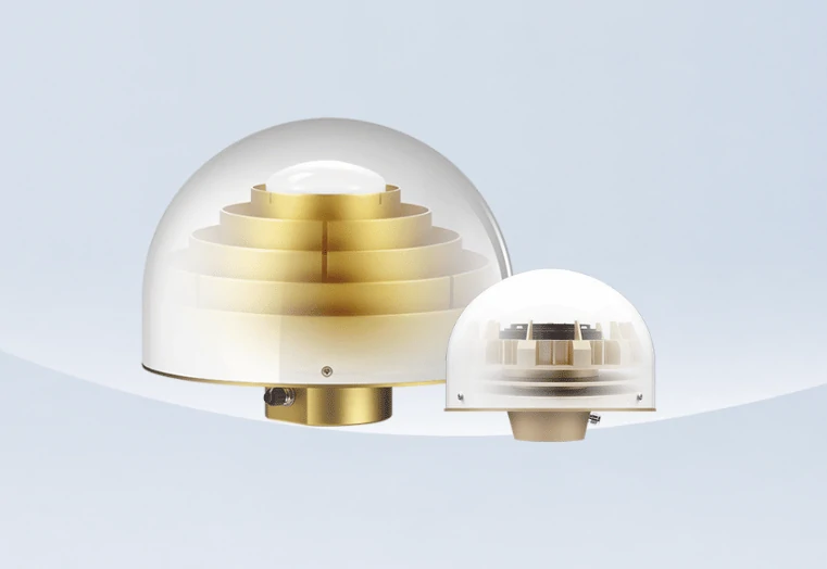
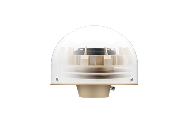
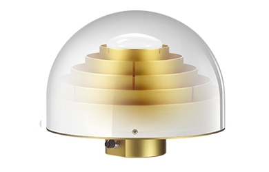
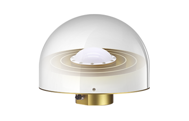
Harxon’s current choke ring range illustrates the practical differences between three formats:
| Design | Example Model | Approximate Size | Maximum Weight | Practical Selection Focus |
|---|---|---|---|---|
| 3D choke ring | HX-CGX601A | Φ379 × 312 mm | ≤10.5 kg | Full-size permanent stations with adequate mounting space and load capacity |
| 2D choke ring | HX-CGX606A | Φ322 × 261 mm | ≤5.6 kg | Fixed installations seeking lower height and weight |
| Mini choke ring | HX-CGX611A | Φ185 × 148 mm | ≤2.5 kg | Space- or load-constrained reference and monitoring installations |
When to Consider a Full-Size 3D Choke Ring
A full-size 3D design is a logical candidate for a permanent reference station with a strong support structure, sufficient clearance and demanding low-elevation or multipath requirements. The full-size option supports multi-constellation, multi-frequency GNSS and L-band signals and is designed for long-term outdoor installation.
Its larger structure should be evaluated together with mounting load, access for installation and future maintenance. It should not be selected merely because 3D appears to represent a higher tier. The project still needs matching calibration data and relevant performance evidence.
When a 2D Choke Ring Is More Practical
A 2D design can be useful when the project still calls for a choke ring antenna but roof loading, support height or installation handling makes a full-size 3D unit less practical. The 2D option retains broad GNSS and L-band coverage while reducing both height and weight.
This format should be viewed as a different mechanical solution, not automatically as a lower-performance version. Compare phase center information, axial ratio, elevation patterns and calibration records under equivalent conditions.
When to Choose a Mini Choke Ring
A mini design is appropriate when the mounting platform is small, the support cannot carry a heavier antenna or the existing station structure has strict dimensional limits. The mini option provides a compact format for fixed reference and high-precision monitoring applications while offering phase center repeatability information and recognized calibration listings.
“Mini” describes the mechanical format. It does not, by itself, prove that every performance characteristic is weaker than that of a larger product. The correct question is whether its measured behavior satisfies the project requirements within the available installation envelope.
What Size Alone Cannot Tell You
Diameter, weight, ring count and the labels 3D, 2D or mini cannot predict final positioning accuracy. Compare phase center variation, repeatability, axial ratio, low-elevation gain, multipath behavior and receiver output under the same conditions.
Final results also depend on the receiver, corrections, cable, installation, local environment and data processing. For that reason, a smaller antenna that fits the station and has appropriate performance evidence may be a better choice than a larger design that creates mounting or integration problems.
Check Receiver and Installation Compatibility
Match LNA Gain, Power and Cable Length
Verify the antenna operating voltage and current against the receiver’s antenna power output. Review LNA gain, noise figure, cable type and total cable loss as one system.
More gain is not automatically better. Insufficient gain can leave too little signal margin after a long cable, while excessive gain may overload a receiver front end in some configurations.
Use the actual cable route rather than an estimated straight-line distance. Include connectors, adapters, surge protection devices and any additional losses in the calculation. The antenna and cable should be selected together rather than treated as separate components.
Confirm Connectors and Mounting
Check both ends of the RF connection. A TNC female antenna interface, for example, must be matched to the correct cable assembly and receiver connector without unnecessary adapters.
Confirm the mounting thread, bracket dimensions, antenna reference point, levelling method and cable strain relief. The support should keep the antenna stable and level without placing cable tension on the connector.
Installation geometry must also allow surveyors to measure antenna height consistently from the defined reference point. An accurate calibration file cannot compensate for an inconsistent or incorrectly measured installation height.
Evaluate Long-Term Environmental Exposure
For permanent outdoor use, compare the IP rating, operating and storage temperature ranges, radome configuration and resistance to routine rain, dust and sunlight. The three compared Harxon models are designed with IP67 protection, but the complete station must also protect connectors, cable entries, adapters and surge components.
Projects involving marine corrosion, extreme icing, unusual wind loading or heavy snow should request application-specific environmental evidence rather than assuming that a general IP rating covers every exposure.
Maintenance access also matters. Consider whether the radome, cable connection and mounting hardware can be inspected or replaced without disturbing the reference point or requiring the entire station structure to be rebuilt.
Verify Calibration and Performance Evidence
Before approving a model, check that the calibration file corresponds to the complete installed configuration. Confirm the exact model, radome, antenna reference point, orientation, calibration method and date.
Where NGS, IGS or another recognized listing is required, verify the individual entry rather than relying on a general statement about the product family. Different versions or radome combinations may not share identical calibration data.
Review the information most relevant to the application:
- Phase center offset
- Phase center variation
- Phase center repeatability
- Gain by elevation angle
- Axial ratio
- VSWR
- LNA gain
- Noise figure
- Out-of-band rejection
- Environmental test results
A longer specification sheet is not necessarily more useful. Each parameter should answer a specific project requirement or site risk.
When comparing 3D, 2D and mini designs, use the same receiver, cable length, power supply, mounting height, site, satellite signals and processing method whenever possible. Without equivalent conditions, published specifications can support initial screening, but they cannot establish an absolute performance ranking.
Final Choke Ring Antenna Selection Checklist
Before placing an order, confirm the following:
- Is the antenna intended for a permanent station or a mobile system?
- How severe is the site’s multipath exposure?
- Are specific NGS, IGS or other calibration records required?
- Which constellations, bands and correction services must be supported?
- Which design fits the available space and structural load?
- Are receiver power, LNA gain and cable loss compatible?
- Do the connector, mounting thread and reference point fit the station?
- Does the environmental protection match the installation?
- Does the calibration match the exact model and radome?
- Were competing products evaluated under comparable conditions?
Conclusion
Choosing a choke ring antenna is a system-matching decision, not a search for the largest structure or the longest specification sheet. Begin with the application, site multipath and calibration needs. Then match GNSS coverage, phase center evidence, receiver power, cable loss, mounting limits and environmental exposure. A 3D, 2D or mini design can each be the right choice when its measured performance and mechanical format fit the same clearly defined project requirements.
FAQ
Is a choke ring antenna necessary for every RTK base station?
No. An open site with limited multipath may perform well with a suitable geodetic antenna. Choke ring designs are more compelling when the project involves severe reflections, long-term reference data, monitoring or a specified calibration requirement.
Is a 3D choke ring always more accurate than a 2D or mini design?
No. The structure name alone does not establish positioning accuracy. Compare phase center data, low-elevation behavior, axial ratio, calibration and controlled test results for the exact models being considered.
Why is phase center calibration important?
Carrier-phase measurements refer to the antenna’s electrical phase center, which can vary with signal direction and frequency. Correct calibration supports consistent antenna height interpretation and more reliable comparison between stations and observation periods.
Can higher LNA gain improve GNSS positioning accuracy?
Not directly. LNA gain helps compensate for downstream cable loss, but the correct value depends on the receiver, cable and other RF components. Excessive or insufficient gain can reduce system margin rather than improve positioning.
What should be tested before final installation?
Verify receiver power, signal tracking, cable loss, connector integrity, antenna levelling, reference-point measurement and data quality at the actual site. For critical projects, compare shortlisted antennas under the same hardware, mounting and processing conditions.