Introduction
Choosing a high-precision GNSS vehicle antenna involves more than comparing gain, frequency bands or enclosure ratings. The antenna must match the receiver, correction method, vehicle architecture and operating environment while fitting mechanical and RF integration constraints. As an established developer of high-precision positioning and vehicle antenna solutions, Harxon approaches antenna selection as a system-level engineering decision. This six-step checklist helps automotive engineers define requirements, compare suitable antenna designs and establish clear approval criteria before committing to a production configuration.
Quick Answer
Begin with the required positioning accuracy, continuity, correction method and operating environment. Confirm that the antenna supports the receiver’s constellations, frequency bands, power supply and input range. Then compare phase-center stability, radiation pattern, axial ratio, filtering and multipath resistance. Select an external, embedded or integrated structure that fits the available ground plane, mounting position and cable route. Finally, confirm environmental durability, manufacturing consistency and target-vehicle qualification. The right antenna is the design that meets the complete vehicle requirement, not simply the model with the highest standalone gain.
Step 1 — Define the Vehicle Positioning Requirements
Antenna selection should begin with a positioning requirement, not with a product data sheet. Different vehicle applications may require standard navigation, lane-level positioning, decimeter performance or RTK-based high-precision positioning.
The required performance must also be linked to the actual operating environment. An autonomous vehicle operating in mixed urban traffic has different antenna requirements from an agricultural machine working mainly in open fields.
Define Accuracy and Availability Targets
Specify the vehicle-level targets that the GNSS system must support, including:
- Horizontal and vertical accuracy
- RTK fixed-solution availability
- Maximum acceptable positioning interruption
- Time to first fix
- Recovery time after temporary signal blockage
- Required performance at low and high vehicle speeds
- Availability in open, suburban and obstructed environments
Antenna specifications should then be assessed according to how well they support these targets.
Confirm the Correction Method
Determine whether the positioning system will use:
- Network RTK
- Local base-station RTK
- PPP
- Satellite-based augmentation
- Sensor fusion without external corrections
The correction method affects the signals that must be supported. For example, a system receiving satellite augmentation through L-band requires compatible antenna and receiver coverage.
Separate Antenna Capability from Positioning Accuracy
A high-precision GNSS antenna helps preserve signal quality, but it cannot independently guarantee centimeter-level positioning.
Final performance also depends on:
- GNSS receiver capability
- Correction-data availability
- Satellite geometry
- Vehicle installation
- Cable loss
- Receiver configuration
- IMU or wheel-sensor integration
- Positioning algorithms
The antenna should therefore be selected as one part of the complete positioning architecture.
Step 2 — Match the Antenna to the Receiver
Once the positioning requirement is defined, confirm functional and electrical compatibility between the antenna and receiver.
Confirm Constellations and Frequency Bands
List the exact signals used by the receiver, such as:
- GPS
- BeiDou
- Galileo
- GLONASS
- QZSS
- SBAS
- L-band augmentation
Then confirm coverage across the required L1, L2 and L5 frequencies.
The description “multi-band GNSS antenna” is not sufficient for approval. Coverage should be verified band by band because different antenna models may support different combinations.
Additional frequency coverage is useful only when the receiver and positioning algorithm can use those signals.
Check the Active Antenna Interface
For an active automotive GNSS antenna, verify:
- Operating voltage
- Current consumption
- LNA gain
- Noise figure
- Nominal impedance
- Receiver bias supply
- Connector type
- Pin arrangement
- DC protection
- Filtering before the LNA
The gain value must be considered together with receiver sensitivity and cable loss. Insufficient gain may leave too little signal at the receiver input, while excessive gain may overload the front end or amplify unwanted signals.
Calculate the Complete RF Link
Evaluate the full signal path:
Antenna element → Filter → LNA → Cable → Connector → Receiver
Include:
- Cable type
- Cable length
- Insertion loss by frequency
- Number of connectors
- Adapters or extension cables
- Manufacturing tolerances
Cable length should be defined during antenna selection rather than after the vehicle layout has been finalized.
Step 3 — Compare High-Precision Antenna Performance
Peak gain alone does not describe whether an antenna is suitable for carrier-phase positioning on a moving vehicle.
Review Phase-Center Stability
For RTK and other carrier-phase applications, review phase center offset and phase center variation across the required frequency bands.
Stable phase-center behavior helps maintain a consistent relationship between the antenna and the vehicle reference point, such as:
- Rear-axle center
- Vehicle coordinate origin
- IMU reference frame
- Sensor-fusion reference point
Consistency across frequencies and production units is particularly important when the same calibration must be applied across multiple vehicles.
Evaluate the Radiation Pattern
Review antenna performance across the complete upper hemisphere rather than relying on maximum zenith gain.
Important characteristics include:
- Horizontal pattern uniformity
- Low-elevation tracking
- Gain variation by azimuth
- Gain roll-off toward the horizon
- Sensitivity to vehicle heading
- Pattern consistency across required bands
A balanced radiation pattern can support more consistent satellite visibility as the vehicle changes direction.
Review Axial Ratio and Multipath Resistance
GNSS antennas receive right-hand circularly polarized satellite signals. Axial-ratio performance across elevation and azimuth angles can therefore influence resistance to reflected signals.
Compare:
- Axial ratio at zenith and lower elevations
- Multipath rejection characteristics
- Pattern control below the horizon
- Phase-center stability near reflective structures
- Performance across all required frequencies
An antenna that performs well at one frequency or one elevation angle may not provide equally stable performance across the full positioning system.
Step 4 — Plan RF Coexistence Before Selecting the Final Design
Modern vehicles may combine GNSS with cellular, Wi-Fi, Bluetooth, C-V2X, DSRC, UWB, AM/FM and other wireless systems.
A high-precision GNSS antenna must operate within this shared RF environment.
Review Filtering and Out-of-Band Rejection
Assess the antenna’s ability to reject strong signals outside the required GNSS bands.
Relevant characteristics include:
- Pre-LNA filtering
- Out-of-band rejection
- LNA linearity
- Resistance to front-end saturation
- Isolation from nearby communication antennas
- Support for required GNSS frequencies without excessive attenuation
Filtering should protect the receiving chain without weakening wanted GNSS signals.
Define Antenna Separation Requirements
Identify all antennas that may be installed on the roof, inside a shark-fin enclosure or behind vehicle panels.
The integration review should include:
- Physical antenna spacing
- Orientation
- Cable separation
- Shared ground structures
- Mutual coupling
- Transmitter power
- Simultaneous operating states
For multifunction antennas, the integration design must balance compact packaging with adequate isolation between navigation and communication elements.
Include Vehicle Electronics in the RF Architecture
Potential noise sources should be considered during the antenna selection stage, including:
- DC/DC converters
- Electric motors
- Inverters
- High-voltage systems
- Displays
- Cameras
- Computing platforms
- Data cables
- Switching power supplies
An antenna with suitable filtering can reduce RF risk, but it does not replace complete vehicle-level EMC design.
Step 5 — Select the Appropriate Vehicle Antenna Structure
Electrical performance must be considered together with styling, packaging, assembly and service requirements.
External Roof-Mounted Antennas
An external roof-mounted antenna generally offers good sky visibility and fewer surrounding materials.
It may be suitable when:
- Positioning performance has priority over concealed styling
- A suitable mounting surface is available
- Weather sealing can be maintained
- The antenna can be placed away from obstructions
- Service or replacement access is required
Possible mounting methods include screw, magnetic and adhesive installation, depending on the application and antenna design.
Embedded Antennas
An embedded antenna can support a low-profile exterior design, but its performance depends heavily on nearby materials.
Evaluate:
- Panel material
- Panel thickness
- Metallic coatings
- Heating elements
- Brackets
- Roof curvature
- Nearby wiring
- Distance from electronic modules
The antenna should be characterized in the intended enclosure rather than only in free space.
Integrated and Shark-Fin Antennas
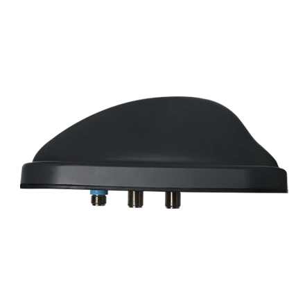
Integrated antennas may combine GNSS with 4G, 5G, C-V2X, DSRC, Wi-Fi, Bluetooth, UWB or AM/FM functions.
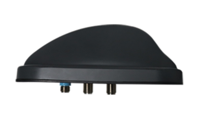
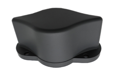
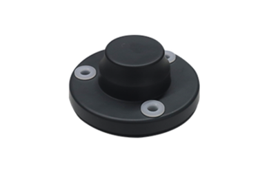
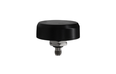
Harxon's vehicle antenna range includes low-profile standalone structures, radome designs and integrated shark-fin configurations. Selection should be based on the required functions, available installation space, RF isolation and vehicle styling rather than treating these structures as interchangeable options.
Evaluate the Ground Plane
The ground plane can affect:
- Antenna impedance
- Resonant frequency
- Radiation pattern
- Gain distribution
- Axial ratio
- Directional balance
Confirm the actual roof material and available metal area. Composite roofs, panoramic glass, sunroofs and asymmetric mounting surfaces may require a different antenna structure or a dedicated ground-plane design.
Confirm Mechanical Integration
The final selection should also satisfy:
- Mounting strength
- Connector retention
- Cable bend radius
- Strain relief
- Water sealing
- Wind resistance
- Assembly sequence
- Service access
- Exterior styling
- Production tolerances
Antenna selection is incomplete until both RF and mechanical interfaces are defined.
Step 6 — Establish Qualification and Approval Criteria
The final step is not general troubleshooting. It is confirming that the selected antenna design meets the project’s documented acceptance requirements.
Verify Model-Specific Environmental Ratings
Review environmental specifications for the exact antenna model, including:
- Operating and storage temperature
- Ingress protection
- Vibration
- Mechanical shock
- Humidity
- Salt spray or corrosion resistance
- UV exposure
- Chemical resistance
- Connector sealing
Do not apply the specifications of one model to an entire product family.
For example, the Harxon HX-CVX608A is intended for high-dynamic vehicle applications and offers pre-filtered LNA options together with screw or magnetic mounting. These model-specific characteristics should be compared directly with the project requirement.
Define the Candidate Comparison Matrix
Compare shortlisted antennas under the same criteria:
| Selection Area | Required Evidence |
|---|---|
| Signal coverage | Supported constellations and frequency bands |
| Receiver interface | Voltage, current, gain, noise figure and impedance |
| Precision performance | Phase-center and radiation-pattern data |
| Multipath control | Axial ratio and low-elevation characteristics |
| RF coexistence | Filtering, rejection and isolation requirements |
| Mechanical integration | Dimensions, mounting, connector and cable options |
| Environmental reliability | Model-specific qualification data |
| Production readiness | Sample consistency, customization and supply capability |
This prevents one attractive specification from outweighing weaknesses elsewhere in the design.
Validate the Production Configuration
Qualification should use the intended production configuration, including:
- Final antenna model
- Final enclosure
- Approved mounting position
- Production cable length
- Production connectors
- Vehicle roof or panel material
- Nearby antennas
- Active communication systems
- Final receiver configuration
Prototype performance cannot automatically be transferred to a production design when the enclosure, cable or installation changes.
Define the Approval Decision
Approve the antenna only when:
- The positioning requirement is documented.
- Signal coverage matches the receiver and correction method.
- LNA, power and RF-link requirements are compatible.
- Phase-center and radiation characteristics support the accuracy target.
- The structure fits the vehicle packaging and ground plane.
- RF coexistence requirements have been addressed.
- Environmental ratings meet the project specification.
- The final production configuration passes vehicle-level qualification.
Final Selection Checklist
Before approving a high-precision GNSS vehicle antenna, confirm:
- Required accuracy and availability are measurable.
- Required GNSS and augmentation signals are supported.
- Receiver voltage and input range match the active antenna.
- Cable and connector losses are included in the RF budget.
- Phase-center stability is suitable for carrier-phase positioning.
- Radiation pattern and axial ratio meet the operating requirement.
- Filtering supports the intended vehicle RF environment.
- The antenna structure fits the available ground plane and enclosure.
- Environmental ratings apply to the exact selected model.
- Qualification uses the final production configuration.
Conclusion
A high-precision GNSS vehicle antenna should be selected through a structured integration process rather than by comparing gain or frequency coverage alone. The final choice must align with the positioning target, receiver interface, antenna performance, RF environment, vehicle structure and environmental requirements.
By defining approval criteria before selecting a model, engineers can compare candidates consistently and avoid committing to an antenna that performs well as a standalone component but does not fit the complete vehicle architecture.
FAQ
What documents should an antenna supplier provide during selection?
Useful documents may include frequency coverage, radiation patterns, axial-ratio data, phase-center information, LNA specifications, cable options, connector drawings, mechanical dimensions and environmental qualification results. Required documentation depends on the project and antenna type.
Should external and embedded antennas be compared using the same data?
Their basic RF characteristics can be compared, but embedded antennas must also be evaluated within the intended enclosure and surrounding materials. Free-space results may not represent their installed behavior.
When is a multifunction vehicle antenna more suitable than separate antennas?
A multifunction antenna may be suitable when roof space, styling or assembly efficiency is important. Separate antennas may offer greater flexibility in placement and isolation. The decision depends on the required wireless functions and integration constraints.
Why does production-unit consistency matter for high-precision GNSS?
Variations in tuning, gain, radiation pattern or phase-center behavior may reduce repeatability across vehicles. Production consistency is therefore important when one calibration or positioning configuration will be used across a fleet.
What additional factors apply to dual-antenna positioning systems?
Dual-antenna systems require suitable antenna spacing, consistent cable paths, correct orientation and an accurately defined baseline relative to the vehicle coordinate system. Both antennas should also have compatible electrical and phase characteristics.