Introduction
GNSS survey accuracy depends on more than the receiver reaching a fixed solution. The measured coordinate must be transferred correctly from the antenna’s electrical phase center to the survey mark, and errors in antenna height, the antenna reference point or the selected calibration model can create systematic elevation differences. This is why high-precision antenna specialists such as Harxon treat phase-center behavior, mechanical reference points and calibration data as part of the measurement system rather than optional specifications. This guide explains how ARP, PCO and PCV work together, how to measure antenna height correctly and what to verify before accepting survey results.
Quick Answer
A GNSS receiver measures signals at the antenna phase center, while the surveyor usually needs the coordinate of a ground mark or instrument reference point. The software connects these points by combining the measured antenna height, the antenna reference point (ARP), phase center offset (PCO) and phase center variation (PCV). A wrong height creates a direct setup bias; a wrong antenna or radome model applies incorrect frequency- and direction-dependent corrections. Use the exact antenna entry, confirm whether height is vertical or slant, measure to the defined ARP and validate the setup through repeated observations on a known point.
Why Antenna Setup Errors Affect Survey Elevations
A GNSS receiver does not directly observe the coordinate of the survey mark beneath the tripod or pole. Carrier-phase measurements are made at electrical reception points associated with the antenna.
The final survey coordinate therefore depends on a chain of relationships:
Survey mark → measured antenna height → antenna reference point → calibrated phase center → GNSS observation
An error at any stage can affect the reported coordinate.
For example:
- Measuring to the wrong physical point changes the antenna height.
- Entering a slant measurement as a vertical height introduces a geometric error.
- Selecting a similar but incorrect antenna model applies the wrong phase-center correction.
- Ignoring a radome designation may use calibration data for a different antenna configuration.
- Replacing a mount or adapter changes the distance between the mark and the ARP.
- Reinstalling the antenna with a different orientation may matter when azimuth-dependent calibration values are used.
These errors may remain present even when the receiver reports an RTK fixed solution. Fixed status indicates that carrier-phase ambiguities have been resolved; it does not confirm that antenna height, ARP or calibration information has been entered correctly.
Why Height Results Often Reveal the Problem First
Antenna setup errors are often most visible in the vertical component because the antenna is installed directly above the survey point and much of the mechanical and phase-center relationship is expressed along the antenna’s vertical axis.
If repeated observations produce stable horizontal coordinates but a consistent elevation difference, check:
- The entered antenna height.
- The selected measurement method.
- The physical ARP.
- The antenna and radome code.
- The mount and adapter dimensions.
- Whether calibration corrections are being applied once or twice.
The antenna should not be replaced until these setup variables have been verified.
What Is the Antenna Reference Point?
The antenna reference point, or ARP, is the physical point on the antenna to which its calibration values are referenced.
It is commonly located on the antenna centerline at or near the mounting surface. Depending on the design, the ARP may be defined as:
- Bottom of the antenna mount.
- Bottom of the ground plane.
- Bottom of a choke ring.
- Top of a pole or mounting interface.
- Another manufacturer-defined mechanical surface.
The ARP is not automatically:
- The top of the radome.
- The visual center of the antenna.
- The connector location.
- The point where a tape happens to touch the housing.
- The electrical phase center.
Always use the antenna drawing, calibration record or manufacturer-defined reference point for the exact model.
Why the ARP Must Be Identified Before Measuring Height
Suppose the field team measures from the survey mark to the bottom edge of the housing, but the software assumes the height was measured to the bottom of the mount. The difference between those two points becomes part of the calculated coordinate.
The receiver cannot identify this physical mistake. It simply processes the value entered by the operator.
Before field deployment, the operating procedure should therefore specify:
- The exact point on the antenna used for height measurement.
- Whether that point is the ARP or a separate slant-height reference.
- The measurement method selected in the controller.
- Any mount or adapter included in the height.
- The unit and precision used for recording the measurement.
A photograph or diagram of the measurement point can help different operators reproduce the same setup.
What Are PCO and PCV?
The electrical phase center is the effective location associated with signal reception. It is not necessarily located at the antenna’s geometric center, and it is not always identical for every GNSS frequency or satellite direction.
Calibration describes this behavior through PCO and PCV.
Phase Center Offset
Phase center offset, or PCO, is the average displacement between the ARP and the antenna’s electrical phase center for a particular frequency.
It may be expressed through north, east and up components.
PCO is frequency-dependent. GPS L1, GPS L2, Galileo E1, BeiDou B1 and other signals may therefore have different phase-center offsets.
A multiband receiver does not treat the antenna as having one universal electrical point. The processing system uses the appropriate calibration values for the signals involved in the solution.
Phase Center Variation
Phase center variation, or PCV, describes how the apparent phase center changes as the direction of the incoming satellite signal changes.
PCV may depend on:
- Satellite elevation.
- Satellite azimuth.
- GNSS constellation.
- Signal frequency.
- Antenna orientation.
- Antenna and radome combination.
A one-dimensional calibration may describe variation by elevation angle. A two-dimensional calibration can describe variation by both elevation and azimuth.
This is why phase-center stability is important in survey and geodetic antennas. The more predictable the response is across the sky, the more consistently the calibration model can relate measurements to the ARP.
Phase Center Correction
The complete correction applied during processing is sometimes described as the phase center correction, or PCC. It combines the projected PCO with the direction-dependent PCV for the satellite being observed.
Surveyors normally do not calculate this correction manually. The controller, receiver or post-processing software applies it after the correct antenna model has been selected.
Do not manually add a published offset unless the equipment workflow specifically requires it. Otherwise, the same correction may be applied twice.
How ARP, PCO and PCV Work Together
These terms describe different parts of one coordinate-transfer process.
| Item | What It Represents | How It Is Used |
|---|---|---|
| Antenna height | Distance from the survey mark to a defined antenna point | Connects the ground point to the antenna installation |
| ARP | Physical reference point on the antenna | Starting point for antenna calibration values |
| PCO | Average offset from ARP to the electrical phase center | Corrects the basic frequency-specific phase-center position |
| PCV | Change in phase response with signal direction | Corrects elevation- and possibly azimuth-dependent behavior |
| Antenna model | Software entry containing calibration information | Tells the system which corrections to apply |
| Radome code | Identifies the calibrated antenna and radome combination | Prevents use of calibration values for a different configuration |
The workflow can be understood in three stages:
- Measure from the survey mark to the defined physical reference.
- Use the correct measurement method to determine the ARP height.
- Apply the antenna model to relate the ARP to the electrical phase observations.
Changing one part of this chain may require the setup to be reviewed again.
Vertical Height vs Slant Height
Antenna height may be measured vertically or along a slope. These methods are not interchangeable.
Vertical Antenna Height
Vertical height is the direct vertical distance between the survey mark and the specified reference point.
It is commonly used with:
- Fixed-height survey poles.
- Precisely measured tripods.
- Permanent monuments.
- Mounting systems with a known vertical dimension.
A fixed-height pole can simplify field procedures, but only when the pole length, tip, locking mechanism and antenna reference point are verified.
Slant Antenna Height
Slant height is measured diagonally from the survey mark to a manufacturer-defined point on the antenna or mount.
The controller may convert this value into a vertical height using:
- The antenna radius.
- The height of the measurement point relative to the ARP.
- The geometry stored for the selected antenna.
- The chosen slant-height method.
A tape measurement to an arbitrary point on the radome is not a valid slant height. The software must know exactly where the tape was placed.
A Reliable Field Measurement Procedure
For every temporary base or tripod setup:
- Identify the required measurement point before setting up.
- Confirm whether the controller expects vertical or slant height.
- Measure after the tripod, tribrach and antenna are secured.
- Record the value and measurement method.
- Measure again independently.
- Check that both readings agree within the project tolerance.
- Recheck the height before dismantling the station.
If the two measurements differ, resolve the cause rather than averaging them automatically.
Select the Exact Antenna Model in Survey Software
Choosing the antenna model is not an administrative detail. It determines which PCO and PCV values the processing system applies.
Check the following fields:
- Manufacturer.
- Exact model number.
- Antenna code.
- Radome code.
- Calibration type.
- Measurement method.
- ARP definition.
- North orientation requirement.
Do not select a model only because its name looks similar. Product variants may use different housings, ground planes, antenna elements or radomes.
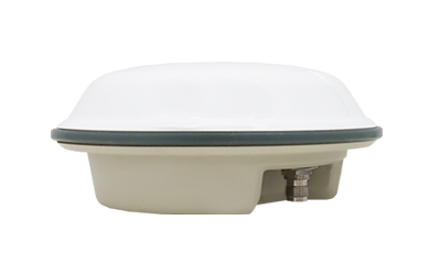
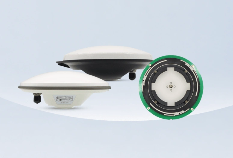
For example, a survey antenna such as the Harxon HX-CSX601A should be matched to its exact supported database entry rather than a generic Harxon survey antenna or another model in the same family. The controller entry, antenna label and calibration documentation should refer to the same hardware.
Check the Software Database Before Fieldwork
Survey controllers and processing packages do not always contain the same antenna database version.
Before approving a new antenna:
- Confirm that the exact model is available.
- Check whether a firmware or database update is required.
- Verify that the correct radome option is listed.
- Confirm that field and office software use compatible naming.
- Check how the model will be written into the RINEX file.
- Document any imported calibration file.
If the exact model is unavailable, do not silently substitute a similar antenna. Confirm the correct procedure with the equipment or antenna supplier.
Explore Harxon Survey GNSS Antennas
What to Check After Changing the Antenna or Mount
Replacing an antenna does not only change the RF component. It may change the physical reference system used by the survey.
Review the setup after changing:
- Antenna model.
- Radome.
- Tripod.
- Pole.
- Tribrach.
- Quick-release adapter.
- Thread adapter.
- Mounting plate.
- Protective enclosure.
- Extension pole.
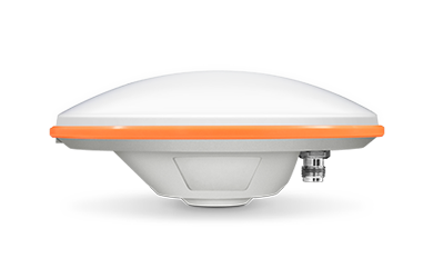
A choke ring antenna such as the Harxon HX-CGX601A has a different physical structure and intended installation from a portable rover antenna. Its mounting interface, ARP, calibration entry and height procedure should be documented as a separate setup rather than inherited from another antenna.
Do Not Reuse the Previous Height Automatically
Even when the tripod has not moved, replacing the antenna or adapter may change:
- The ARP elevation.
- The slant measurement point.
- The total mechanical height.
- The software measurement method.
- The antenna orientation.
Measure the completed setup again and update the station record.
Check Antenna Orientation
Some calibration models contain azimuth-dependent PCV values. In these cases, antenna orientation becomes part of the measurement setup.
Where the antenna has a north reference mark:
- Identify the correct mark.
- Align it consistently.
- Record the orientation.
- Avoid using the cable direction as a substitute unless documentation defines it that way.
Orientation consistency is particularly important for permanent stations, deformation monitoring and repeated high-precision occupations.
Verify the Setup on a Known Control Point
Documentation narrows the risk of error, but repeated field validation confirms whether the complete procedure works.
Establish a Controlled Test
Use a control point with reliable coordinates and keep the following unchanged:
- Receiver.
- Firmware.
- Correction source.
- Processing method.
- Pole or tripod.
- Controller settings.
- Observation duration.
Then test the antenna setup.
Record:
- Antenna model.
- Radome code.
- Height value.
- Height method.
- ARP.
- Mounting components.
- Orientation.
- Start and end times.
- Horizontal result.
- Vertical result.
Repeat the Entire Setup
One successful observation does not prove repeatability.
Between tests:
- End the survey.
- Remove or reposition the equipment.
- Reinstall the antenna.
- Remeasure the height.
- Restart or reinitialize the receiver.
- Reoccupy the control point.
- Compare the new result with the previous result.
This process tests both the antenna system and the operator’s ability to reproduce the setup.
Separate Constant and Variable Errors
A nearly identical elevation difference in every test may indicate:
- Incorrect antenna height.
- Wrong ARP.
- Wrong antenna model.
- Incorrect adapter dimension.
- A consistent processing configuration error.
Results that change between occupations may indicate:
- Tripod or pole instability.
- Inconsistent slant measurements.
- Antenna orientation differences.
- Loose mounting hardware.
- Multipath or changing site conditions.
The distinction helps determine whether the problem is systematic or setup-dependent.
GNSS Antenna Setup Checklist
| Check | What to Verify |
|---|---|
| Antenna identity | Manufacturer, exact model and hardware variant |
| Radome | Correct radome designation or NONE entry |
| ARP | Physical reference point confirmed from the model documentation |
| Height method | Vertical or slant method selected correctly |
| Measurement point | Tape or pole references the defined physical point |
| PCO and PCV | Correct calibration model available for the required signals |
| Software | Field and office packages use the same antenna identification |
| Mount | Adapters and mounting components are included correctly |
| Orientation | North reference aligned and recorded where required |
| Field record | Model, height, method, mount and orientation documented |
| Validation | Setup repeats within project tolerances on a known point |
Conclusion
ARP, PCO and PCV are not separate theoretical specifications. Together with antenna height and the selected software model, they define how GNSS observations are transferred from the antenna’s electrical response to the survey point.
A fixed solution can still contain a systematic error when the height is measured to the wrong point, the measurement method is misidentified or the wrong antenna calibration is applied. Reliable results therefore require a documented ARP, the exact antenna and radome entry, repeatable mounting and an independent height check.
Harxon’s survey and geodetic antenna solutions are designed around stable phase-center behavior, but that performance can only be used correctly when the field setup and processing model describe the same physical antenna configuration.
FAQ
What Is the Difference Between a Type-Mean and an Individual Antenna Calibration?
A type-mean calibration combines results from multiple antennas of the same model to represent typical behavior. An individual calibration measures one specific antenna. Individual calibration may be required for the most demanding geodetic or monitoring work, while type-mean calibration is commonly used for professional survey operations.
Does Adding a Radome Change the Required Calibration Model?
It can. A radome may affect the antenna’s phase response, especially when its material, thickness or geometry differs from the configuration used during calibration. Use the calibrated antenna-and-radome combination where one is specified rather than assuming the bare-antenna model remains valid.
Should the Antenna Model Be Recorded in RINEX Data?
Yes. Recording the standardized antenna and radome codes allows post-processing software to identify the correct calibration model. A generic or incomplete name may prevent automatic phase-center correction or cause the wrong model to be selected.
Can Replacing the Antenna Cable Change PCO or PCV?
The cable does not normally change the antenna’s published PCO or PCV model, but it can affect the RF signal path through loss, damaged connectors or poor routing. After replacing a cable, verify signal performance without altering the antenna calibration unless the complete antenna assembly is defined and calibrated as one unit.
Does a Fixed-Height Pole Eliminate Antenna Height Errors?
No. It reduces routine measurement work but still depends on the correct pole length, tip condition, locking position, adapter and ARP. A fixed-height pole should be periodically checked and reverified whenever the antenna or mounting hardware changes.