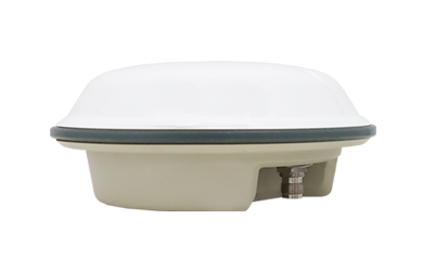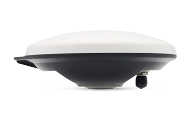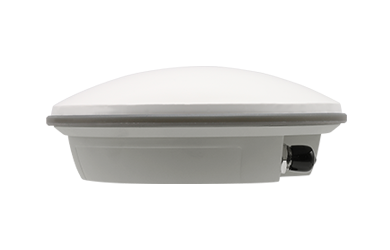
High-precision GNSS antennas play a critical role in positioning, surveying, mapping, autonomous driving, geodetic monitoring, and robotics. Although GNSS modules and receivers continue to improve, the antenna remains the primary element that determines signal quality, stability, multipath rejection, and positioning accuracy. A well-designed GNSS antenna significantly enhances performance, especially in challenging environments.
This guide aims to help you understand how high-precision GNSS antennas are engineered, what performance indicators matter, and which structural factors contribute the most to reliability and accuracy.
Antenna Body: The Foundation of GNSS Performance
The wireless antenna element—also known as the passive antenna or ''antenna body'' — is responsible for receiving and radiating GNSS signals. Its structure has three key components: substrate material, antenna form, and feed-point design.
Substrate Material: Where Performance Starts
The substrate material determines dielectric properties, radiation efficiency, size, and environmental stability. Common GNSS antenna substrate materials include:
Engineering Plastics (εr = 2–3)
-
Light weight
-
Cost-effective
-
Suitable for compact designs
-
Good mechanical stability
FB4M (εr = 3.4–4.7)
-
Higher dielectric constant
-
Enables smaller form factors
-
Improved strength
-
Easy to manufacture
TP/TAP Substrate (εr = 1.2–2.55)
-
Low dielectric loss
-
High stability
-
Better high-frequency performance
-
Popular for multi-band GNSS antennas
Ceramic Materials (εr = 20–100)
-
Ultra-high dielectric
-
Very small size
-
Excellent environmental stability
-
Ideal for L1/L2/L5 compact GNSS antennas
Metal Radomes
For antennas used in automotive, UAV, and geodetic applications, the radome material also influences performance:
-
High strength
-
Weather resistance
-
Good shielding
-
Long service life
Ceramic and metal-based structures usually deliver the highest precision because their dielectric properties remain stable under temperature changes. In Harxon's product development process, we have consistently observed that substrate stability directly correlates with phase-center repeatability.
Antenna Form: Single Layer vs. Multi-Layer Structures
The geometry of the antenna greatly affects its gain, bandwidth, and multipath rejection capabilities.
Single-Layer Antenna (Basic GNSS Patch)
-
Single ceramic patch or board
-
Low cost
-
Easy to produce
-
Suitable for consumer-level GNSS applications
Multi-Layer Antenna
-
Multiple stacked dielectric layers
-
Wider frequency bandwidth
-
Better multipath suppression
-
Supports full-band or multi-band GNSS
Stacked Patch Antenna
-
Metal patch + dielectric + ground
-
High gain
-
Stable phase center
-
Excellent for RTK, surveying, UAV, and precision farming
In high-precision scenarios, multi-layer and stacked patch antennas show clear advantages. In our own Harxon multi-band GNSS antennas, layered structures allow us to control resonant modes more accurately, achieving both wide bandwidth and consistent gain across L1/L2/L5/B1/B2/G1/G2 frequencies.
Feed-Point Structure: The Core of Phase Center Stability
The feed-point configuration dramatically affects:
-
Phase Center Error (PCE)
-
Gain symmetry
-
Axial ratio
-
Multipath resistance
Single Feed
-
Simplest structure
-
Acceptable for low-precision applications
-
Phase center stability around ±2 mm
Dual Feed
-
Reduced phase center variation
-
Better performance in multi-band GNSS
-
Stability within ±1 mm
Multi-Feed
-
Best balance across frequency bands
-
Excellent symmetry
-
Stability within ±0.5 mm or better
The general rule is: the more optimized the feed structure, the better the GNSS antenna's comprehensive performance. In professional-grade antennas like those we design at Harxon, multi-feed systems are essential for centimeter-level RTK accuracy.
PCB Board: The Carrier of Signals and Structure
The PCB is not merely a mounting platform—it influences electromagnetic behavior, mechanical stability, and filtering performance.
A well-designed PCB helps:
-
Improve signal integrity
-
Optimize ground plane effects
-
Lower noise
-
Enhance multi-band consistency
High-precision GNSS antennas often require:
-
Low-loss PCB material
-
Multi-layer routing
-
Carefully designed ground and vias
-
Shielding isolation zones
Inferior PCB design can cause distorted radiation patterns, reduced gain, or a high axial ratio. At Harxon, we treat PCB design as one of the core determinants of antenna quality, not just a mechanical component.
LNA Circuit: Amplifying Weak GNSS Signals
The Low-Noise Amplifier (LNA) is one of the most influential active components because GNSS satellite signals are extremely weak—often below –130 dBm.
The LNA must:
-
Amplify weak signals
-
Maintain low noise figure
-
Provide stable gain across GNSS bands
Key LNA parameters
| Parameter | Importance |
|
Gain |
Ensures adequate signal strength |
|
Noise Figure (NF) |
Lower NF = better sensitivity |
|
1 dB Compression Point |
Prevents distortion under strong interference |
|
Linearity |
Ensures clean amplification |
High-precision applications—RTK, PPP, surveying—cannot tolerate noise figure instability. In Harxon's antennas, multi-stage LNAs are used to achieve optimal gain distribution while maximizing signal purity.
Filter System: Protecting Against Interference
Modern environments are full of wireless noise—from LTE, WiFi, UHF, C-band, and in-vehicle systems. GNSS signals can easily be overwhelmed if filtering is inadequate.
Types of filters commonly used in GNSS antennas
SAW Filters
-
Stable
-
Good band selectivity
-
Effective at narrowband GNSS frequencies
BAW Filters
-
Higher performance than SAW
-
Excellent out-of-band rejection
-
Ideal for L5/B2a signals
LC Filters
-
Simple
-
Low cost
-
Used as secondary filtering stages
Filter Function
-
Reject out-of-band interference
-
Maintain in-band flatness
-
Reduce insertion loss
-
Protect LNA from overload
In Harxon engineering practice, filtering is not optional—it is essential. Strong filtering dramatically improves accuracy in electromagnetic-noisy environments such as cities, ports, agriculture machinery, or autonomous vehicles.
Shielding: The Guardian of Signal Purity
A metal shielding cover protects the LNA and PCB from:
-
EMI (electromagnetic interference)
-
PCB cross-talk
-
Environmental noise
-
Voltage fluctuations
Internal shielding also improves:
-
GNSS positioning stability
-
Multi-band consistency
-
Low-elevation signal capture
High-precision antennas always include a shielding layer. Without it, even a good antenna element can perform poorly in real-world use.
Mechanical Structure & Environmental Reliability
Beyond electrical design, mechanical construction impacts durability and long-term accuracy.
Critical factors include:
-
Radome strength
-
Waterproofing level
-
Thermal stability
-
Vibration resistance
-
UV resistance
For professional surveying, agriculture, and autonomous driving, an antenna must deliver stable performance despite extreme temperature, shock, and long operation times. At Harxon, many of our antennas undergo rigorous environmental testing—temperature cycling, vibration, salt-spray, humidity—to ensure long-term reliability.
What Truly Determines GNSS Antenna Performance?
When evaluating or selecting a high-precision GNSS antenna, consider the following core indicators:
1. Phase Center Stability (PCE)
The most important factor in high-precision applications. Lower PCE = better accuracy.
2. Gain & Elevation Pattern
A stable high-elevation pattern improves sky coverage.
3. Axial Ratio
Low axial ratio improves multipath rejection.
4. Noise Figure of Active Circuit
Lower NF = better sensitivity and signal clarity.
5. Filtering Strength
Strong filtering ensures reliable operation in interference-heavy environments.
6. Environmental Adaptability
Durability directly affects long-term performance.
Through years of development at Harxon, we have confirmed that precision results from the balanced optimization of all structural components—not just one specification. A good GNSS antenna is not defined by gain alone or material alone, but by the harmonious integration of design, electronics, mechanics, and environmental engineering.
Conclusion
The performance of a high-precision GNSS antenna is determined by a complex combination of structural and electronic factors—substrate materials, antenna geometry, feed-point design, PCB layout, LNA amplification, filtering components, and environmental shielding. Each piece contributes to stability, accuracy, and reliability.
Understanding the structural breakdown of GNSS antennas allows engineers, integrators, and product designers to make better decisions—and helps ensure stable, centimeter-level accuracy across diverse applications such as surveying, robotics, agriculture, and autonomous systems.