Navigation without a boundary wire is not a sensor shopping list. The mower still needs a global position reference, a way to track local movement, and a plan for what happens when an input becomes unreliable. RTK GNSS, network RTK, vision, LiDAR, and dual GNSS each provide different information. Sensor fusion can combine those inputs, but it also brings calibration, timing, computing, and fallback decisions into the design. The five combinations below show how OEMs can divide those jobs, where each approach fits, and what to test before settling on a platform.
Robotic Lawn Mower Navigation Technologies Overview
A boundary wire marks the perimeter. Without one, the mower uses GNSS, onboard sensors, or both to locate itself and map its work area. Navigation options have evolved from single positioning or perception methods to product-specific mixes of RTK GNSS, vision, LiDAR, and sensor fusion; there is no standard stack.
RTK/NRTK provides global positioning; NRTK changes correction delivery. Visual SLAM tracks camera motion and builds or reuses a local map; object classification is a separate vision task. LiDAR measures range and geometry. An IMU and wheel odometry add motion data, while supported dual GNSS can provide heading. Sensor fusion combines selected inputs and must handle disagreement or dropouts. No sensor alone covers positioning, mapping, and obstacle perception.
| Sensor or input | What it adds | What it cannot provide alone |
|---|---|---|
| RTK / NRTK GNSS | Global position; NRTK changes correction delivery | Obstacle perception |
| Vision / VSLAM | Camera motion and local map; separate models may classify objects | Global reference or full safety function |
| LiDAR | Range and local geometry | Absolute position by default |
| IMU / odometry | Short-term motion observations | Long-term global position alone |
| Dual GNSS | Baseline heading in supported designs | Obstacle detection |
| Sensor fusion | Combination of selected inputs | Automatic reliability or fault handling |
For GNSS antenna options used on robot platforms, see the GNSS antenna options for robots.
Five Navigation Architectures for Robotic Lawn Mowers
The five routes below split up the navigation jobs in different ways. Use the table to compare what each one contributes and what the mower must support around it.
| Architecture | What it contributes | Main trade-offs | A good fit when… |
|---|---|---|---|
| RTK + Vision / VSLAM | Global position plus camera-based local motion or mapping | Satellite view, corrections, image quality, alignment and timing | The mower needs both a global reference and local visual information |
| NRTK / Cloud RTK + Vision / VSLAM | Network corrections plus camera-based local motion or mapping | Service coverage, data link, correction format and receiver support | Mowers operate across sites with a suitable network connection |
| LiDAR + Vision / VSLAM | Local geometry plus camera features or mapping | Sensor alignment, map drift, scene changes and computing load | The design needs both range and visual cues |
| RTK / NRTK + LiDAR + Vision | Global position plus LiDAR geometry and camera features | More calibration, timing, power, bandwidth and fault handling | Each input serves a defined platform requirement |
| Dual-GNSS RTK + Vision / Sensor | RTK position plus supported baseline heading and another sensor | Receiver mode, rigid baseline, satellite view and corrections | GNSS heading is useful and the antenna spacing fits the chassis |
1. RTK + Vision / VSLAM
RTK gives the mower a global position reference from satellite observations and correction data. The camera adds a local view: visual odometry or SLAM can estimate camera movement and build or reuse a map. If the mower also uses a camera model to recognize obstacles, that is a separate perception function. VSLAM alone is not a complete obstacle-detection or safety system.
This pairing makes sense when the mower needs both a global reference for its virtual work area and visual information for local motion or mapping. The two inputs have different weak points. RTK needs satellite visibility, valid corrections, and ambiguity initialization; visual tracking needs usable image features. Grass texture, repeated patterns, changing light, motion blur, a dirty lens, and seasonal changes can all affect what the camera sees. Test those conditions instead of assuming vision will take over seamlessly if RTK degrades.
Pay particular attention to handoffs between the two estimates. Track RTK solution state and correction age, visual-tracking status and relocalization time, then compare both outputs against a common reference. Timestamp alignment and camera-to-vehicle calibration matter too. Decide how the mower should respond when either estimate goes stale or they disagree; don't count on fusion to hide a bad input.
2. NRTK / Cloud RTK + Vision / VSLAM
Network RTK changes where corrections come from, not what GNSS does. With a local setup, a base station sends correction data to the mower's rover. With NRTK, a service delivers corrections over a supported internet/IP connection and protocol; the link may use cellular service or another suitable connection. That can remove the need for a local base at every site, but it doesn't remove the infrastructure question. Service availability, connectivity, subscription terms, network configuration, correction format, receiver support, and latency still matter.
For mowers used across many sites, network RTK is worth considering when those locations have suitable service coverage. The practical question is simple: can the mower receive compatible corrections where it will operate, and how should it respond if the connection drops?
Test the service across the mower's intended regions and record correction age, dropouts, reconnection time, and receiver solution state. Then check its behavior without corrections: does it slow, stop, or switch to a supported fallback? The positioning stack should flag degraded status to the planner, and the boundary or mapping logic needs a defined response. The receiver must support the service's protocol and correction format. For the antenna and receiver side of the design, see the OEM GNSS antenna integration guide.
3. LiDAR + Vision / VSLAM
LiDAR and cameras don't observe the yard in the same way. A camera provides image features and appearance; LiDAR measures range and geometry. A mapping stack can use both to estimate motion and describe nearby surroundings, but the algorithm determines how. For example, visual odometry may estimate motion while LiDAR scan matching refines it or registers point clouds. “LiDAR plus camera” describes the sensors, not the navigation method by itself.
Vision and LiDAR can support local mapping without a GNSS correction stream, but neither provides a global position reference by default. If repeatable boundaries matter, the mower still needs a way to anchor, initialize, update, and recover its map. Test for drift over longer runs, scenery that changes between sessions, blocked sensors, moving objects, and observations the software cannot confidently match.
Mounting and timing are part of the design, not cleanup work. Check camera-to-LiDAR alignment after assembly, then compare tracking and map consistency across the mower's lighting, vegetation, and site conditions. Include wet or reflective surfaces, low grass, taller plants, and moving foliage in tests; results will vary by sensor and mount. If the mower reuses maps across sessions, test relocalization after the scene has changed.
4. RTK / NRTK + LiDAR + Vision
Here, RTK or NRTK supplies global position, LiDAR describes nearby geometry, and cameras contribute visual features. The design may also use an IMU or wheel odometry; don't assume either is included. Fusion software has to align the observations, decide which ones to use, and handle disagreements.
Putting three sensing modes together gives the mower a global reference plus local geometry and visual information. It doesn't guarantee greater reliability: inputs can share failure conditions, conflict, or arrive late. Each added sensor also uses enclosure space, power, processor capacity, and engineering time. Include a sensor only when it serves a defined requirement, and decide what the mower should do when that input is lost.
During testing, block or delay each input and record whether the mower continues, changes behavior, or recovers as designed. Use the same mower-level limits for every candidate—availability, recovery, power, and temperature. Results from another robot can inform the test plan, but they are not acceptance limits for this mower. The table below lists useful signals to record.
5. Dual-GNSS RTK + Vision / Sensor
A supported dual-GNSS setup can provide heading from the baseline between two antennas. Depending on the design, it may use two receivers or a receiver with a dedicated dual-antenna mode. Either way, the antennas need a fixed relationship and known baseline direction, with suitable satellite visibility, correction handling, and receiver support. Simply mounting two antennas on the mower does not produce a usable heading by itself.
The extra antenna space is worthwhile only if GNSS-derived heading serves a real need and the chassis can hold the baseline geometry. It can provide an orientation observation independent of wheel-derived motion, but it doesn't replace vision, an IMU, or other sensors needed for local mapping or perception. And heading is not obstacle detection.
Treat the baseline as a chassis decision early on. Read the receiver's supported mode and baseline requirements, then check separation, mounting stiffness, relative orientation, ground-plane effects where relevant, cable routing, shared sky view, and RF coexistence. Measure heading availability and variation against a reference during starts, stops, turns, partial sky obstruction, and correction interruptions. A moving-base example for one receiver is not a mower design rule; the selected module and antenna layout set the limits.
How Should an OEM Choose a Navigation Architecture?
Start with the mower's operating requirements, then narrow the stack:
- Where does the mower need a position? Decide whether it needs a global reference, a local map, or both—and how it will represent boundaries and repeatable areas.
- What will it encounter? Note satellite visibility, obstructions, lighting, vegetation, moving objects, and the number of operating regions.
- How will corrections reach it? Compare a local base with network corrections by coverage, connection, format, receiver support, and outage behavior.
- Which sensor handles each job? Treat heading, mapping, and obstacle perception as separate jobs, and choose sensors for each one.
- What fits the mower? Check antenna geometry, sensor fields of view, baseline space, timing, processing, power, thermal limits, and communications.
- What happens when an input drops out? Define acceptance limits from product requirements.
| What to log | Why it matters |
|---|---|
| RTK/NRTK solution state, correction age, outage and recovery time | Shows whether the global-position input is usable through normal and degraded conditions |
| Visual or LiDAR tracking state, local-map consistency, relocalization time | Shows whether local motion and mapping remain observable in the mower's environments |
| Heading availability and deviation against a reference | Separates orientation quality from position quality |
| Sensor timestamps, estimated time offset, and calibration residuals | Reveals alignment errors that can make valid sensors disagree |
| Fusion confidence, rejected measurements, and degraded-mode transitions | Shows how the system responds to conflicts or missing inputs |
| Processor load, power draw, thermal behavior, and communication status | Tests whether the architecture fits the actual embedded platform |
Run the candidates on the same routes. A peak accuracy figure alone won't show how often the mower loses a fix, how long recovery takes, or how much processing and power the stack needs. Set limits for boundary accuracy, heading, coverage, and operating conditions; no single threshold fits every mower. Once you know which GNSS signals the receiver supports, use this dual-band vs. multi-band GNSS antenna guide to compare antenna band options.
Harxon GNSS and RF Hardware Options
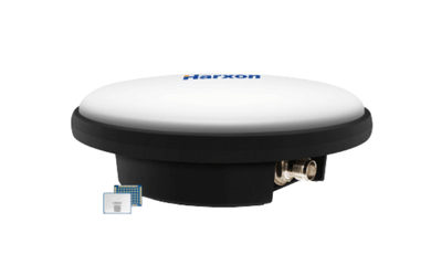
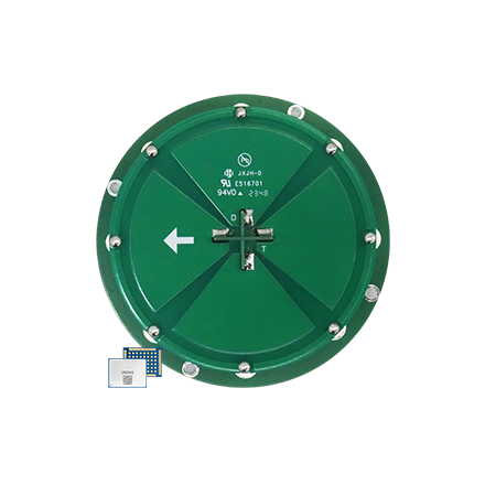
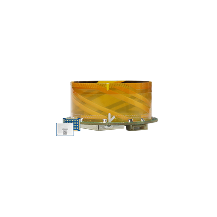
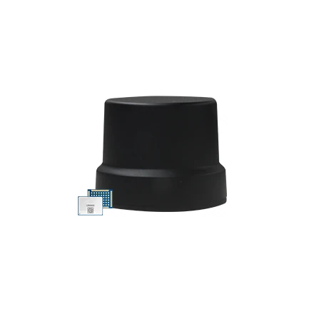
Once you know which navigation jobs the mower must handle, match its GNSS/RF hardware to the receiver, correction link, enclosure, and radios. Harxon’s GNSS/RF hardware portfolio covers these hardware options.
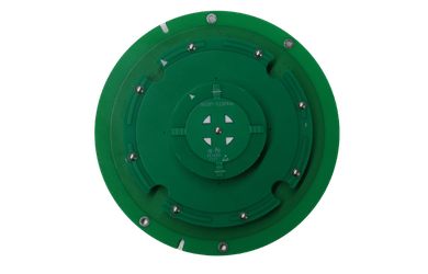
Robot-platform options range from GNSS-only antennas to the Smart Antenna for UAV/Robot category, which integrates an antenna and RTK module, and model-specific multi-function options combining GNSS with supported 4G/5G, Wi-Fi/Bluetooth, or radio functions. Available bands, modules, and radio combinations vary by model.
If the receiver is already selected, start with GNSS-only antenna options; if RTK-module integration is still open, compare the Smart Antenna models. For either path, check the final design against:
- available space and satellite view, plus antenna location and separation;
- required GNSS bands, receiver-supported constellations, and receiver/module interfaces;
- power, mounting, cable and connector routes, nearby radios, and simultaneous radio modes.
Bands and interfaces are model-specific. Match them to the selected receiver, then test RF coexistence in the assembled mower—even when the antenna and RTK module come in one package. Customization can cover antenna structure and size, band/function combinations, interfaces, installation, cables/connectors, and module integration. See the product customization page for those options. This covers the GNSS/RF side of integration; the mower platform still handles cameras, LiDAR, SLAM, fusion, planning, and safety.
Conclusion
There is no best stack for every mower. Choose the one that fits the mower's boundary, environment, correction access, and integration limits, then compare candidate stacks on the same routes—including interruptions and recovery. A sound choice is one that remains within the product's limits when a sensor degrades or a correction link drops.
Discuss Your Mower’s GNSS Integration
Building a robotic mower? Share your receiver or RTK module, target region, and main enclosure or RF constraint when you contact us about GNSS integration. We can discuss antenna options and customization scope.
Robotic Mower Navigation FAQs
What is the difference between RTK and network RTK?
Both use GNSS corrections; the difference is how they reach the mower. A local base sends corrections over a supported link, while network RTK delivers them from a service over the internet. That can avoid a base station at every site, but the service, connection, receiver, and correction format still have to work together.
Can vision replace RTK on a robotic mower?
No, not as a like-for-like substitute. VSLAM estimates camera motion and builds a local map; RTK gives the mower a global position reference. A mower can operate without RTK only if its boundary, localization, and recovery design supports that mode.
Does adding LiDAR and cameras make navigation more reliable?
They can help cover a specific blind spot, provided the software can align and use the extra data. Each sensor also adds calibration, processing, and fallback work. More sensors alone don't guarantee uptime or smooth recovery.
Does dual GNSS detect obstacles?
No. A supported fixed GNSS baseline can provide heading, not obstacle detection. That requires a separate perception system. The receiver must support dual-antenna operation, and the platform must accommodate the baseline geometry.