Smart TVs, streaming devices, and smart-home systems increasingly rely on remotes that do more than send simple button commands. A Bluetooth Low Energy (BLE) connection can support low-power wireless control in a compact handheld device. But the connection is not defined by the radio module alone. The antenna, PCB, battery, enclosure, and the way a user holds the remote all form the RF system that must work together in the finished product.
For a smart remote control, selecting a 2.4 GHz antenna is an integration decision. Start with the available space and radio requirements, then check placement, matching, tuning, and device-level performance on representative units.
Bluetooth Low Energy in Smart Remote Controls
BLE operates in the 2.4 GHz band and can provide a low-power wireless link between a remote control and a compatible host device. In a smart TV or streaming-device system, that link may support control functions that are not practical with a line-of-sight-only interface. In a smart-home remote, it can also be part of a wireless control path for a connected system.
For device teams, the useful question is not simply whether a remote includes Bluetooth. It is whether the complete 2.4 GHz RF path can meet the intended user experience within the remote's physical constraints. The radio, antenna, feed path, ground structure, enclosure, and operating environment all contribute to the result.
In a compact BLE remote, antenna behavior is shaped by the finished device rather than the antenna alone. A component that performs as expected on a reference board can behave differently after it is placed next to the remote's battery, keys, shielding, plastic enclosure, and other electronics. Antenna integration brings those interactions into the layout and mechanical decisions early in development.
Antenna Integration Challenges Inside a Smart Remote
Remote controls have limited internal volume, and nearly every mechanical feature competes for space. The PCB provides the radio circuitry and often part of the antenna's electrical environment. The battery can be a large nearby object. Buttons, conductive contacts, shielding, fasteners, cables, and decorative finishes can change the available placement options. The enclosure material and wall thickness also matter because the antenna must operate inside the finished device rather than in free space.
The user is another part of the operating environment. A hand can be close to the antenna during normal use, so a design should not be evaluated only with an untouched remote on a bench. The goal is not to remove every variable. It is to identify the variables that affect the intended product and include them in the validation plan.
| Integration factor | Engineering question | What to validate |
|---|---|---|
| PCB and ground plane | Does the proposed location provide the ground relationship and clearance needed by the selected antenna concept? | Input match and behavior on the intended PCB. |
| Battery and nearby parts | Which components or metal features are close to the radiator or RF feed? | Whether nearby structure shifts the response or changes repeatability. |
| Buttons and enclosure | Does the final mechanical stack-up change the antenna environment? | Performance with production-representative plastics, keys, and assembly parts. |
| User hand | Is the antenna near the normal grip area? | Link behavior in representative use positions. |
| Other electronics | Are there nearby RF, digital, or power circuits that need to be considered in the layout review? | Whole-device RF behavior under the relevant operating conditions. |
Choose Antenna Placement with the PCB and Mechanical Design
An embedded antenna should be located with the PCB and mechanical team, not after the rest of the remote has been fixed. The proposed position needs to be considered with the available board edge, ground structure, copper clearance, feed routing, battery location, and enclosure features. Moving one of these elements can change the antenna environment.
The best placement for one remote is not automatically the best placement for another. Board size, battery chemistry and shape, key layout, wall thickness, radio module, and target product form factor all vary. A placement review should therefore establish the constraints of the specific remote before the final mechanical and PCB layout are frozen.
Custom Antenna Design and Whole-Device RF Optimization
Smart-remote antenna design starts with the remote dimensions, PCB outline and stack-up, ground arrangement, radio or module interface, proposed antenna location, enclosure materials, battery location, target wireless bands, and intended market. These inputs show whether an existing antenna form factor suits the design or whether a more specific integration approach is needed.
Development is iterative. Integrate the antenna with the product PCB and measure the RF behavior of the complete path. Four activities provide a practical sequence:
- Antenna Placement — Review the selected location against board edge, ground, clearance, feed routing, mechanical parts, and normal user grip.
- Matching — Measure the antenna path on the application PCB and determine whether the interface needs adjustment for the relevant operating band.
- Tuning — Refine the RF response using the actual board and representative mechanical configuration rather than relying only on a component reference board.
- Whole-Device Testing — Evaluate representative assembled units, including the intended enclosure and relevant use conditions, so the team can identify design variation before production planning.
Match and Tune on the Actual Product PCB
The electrical environment of a chip or printed antenna is part of its performance. A result measured on a reference board can change on a remote-control PCB with a different ground plane, feed path, battery, enclosure, and nearby parts. For this reason, matching and tuning should be based on measurements from the application structure.
The matching network should also preserve the ability to make controlled adjustments during development. Its final implementation reflects the selected radio interface and antenna arrangement. It is not a set of universal component values that can be copied between remotes. The goal is a balanced response across the operating band in the assembled product.
Whole-device optimization should also look beyond one engineering sample. Production-representative boards, mechanical parts, and assembly conditions help the team identify build-related variation before production.
Harxon Bluetooth Antenna Solution for Compact Wireless Terminals
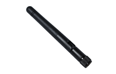
Harxon provides a Wi-Fi / Bluetooth Antenna portfolio for compact wireless terminals. For an OEM remote-control project, the portfolio offers compact antenna options with different form factors and published frequency coverage for the intended radio design.
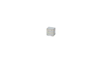
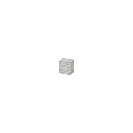
Harxon recommends the DAI2400-5800_W05A compact ceramic chip antenna for compact wireless-terminal integration. The antenna uses an SMD ceramic chip design in a published 3 × 4 × 4 mm package, helping designers preserve PCB space in smart terminals and other space-constrained products. It covers 2400–2500 MHz and 5150–5850 MHz for 2.4 GHz and 5.8 GHz wireless communication. In a BLE smart remote, the 2.4 GHz portion supports the radio path when the selected BLE radio operates in that band. The 5.8 GHz coverage can also support product architectures that require this additional wireless band.
For BLE smart-remote development, the 2.4 GHz radio path must be considered with the radio interface, PCB ground, antenna location, battery, enclosure, user-hand condition, and test requirements. Harxon can support antenna customization and whole-device RF optimization based on these product-specific inputs, helping the design team select an antenna for the finished remote.
Validate the Antenna in the Remote, Not Only on a Reference Board
BLE can provide a useful 2.4 GHz wireless-control path for a compact smart remote, but connection behavior is set in the finished device. Treat antenna placement, matching, tuning, and testing on representative assembled units as one integration task. A compact SMD ceramic antenna can be a practical option when its placement and RF behavior are established on the assembled remote.
Contact Harxon to discuss antenna integration for your BLE smart-remote design.
Frequently Asked Questions
What information helps begin an antenna integration discussion?
A PCB layout, proposed antenna location, and basic battery and enclosure details are usually enough to begin an integration discussion. Additional RF and test information can then be defined for the specific design.
Does a 2.4/5.8 GHz antenna automatically make a remote a dual-band Bluetooth device?
No. The antenna's published coverage is only one part of the design. The selected radio, supported protocols, and RF design determine which wireless technologies and bands the finished remote can use.